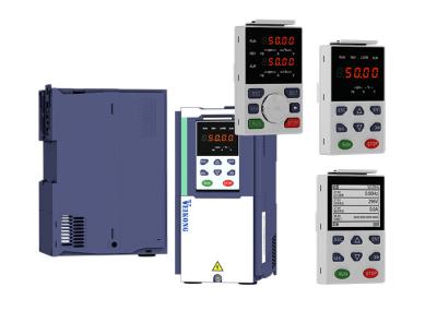
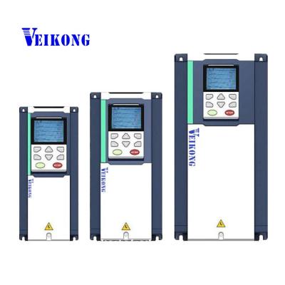
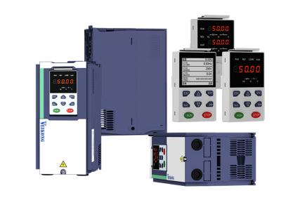
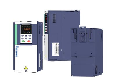
Single phase pump solar pump inverter 220v 2.2kw 4kw 50hz 60hz
Model Range
Drive Model | Related Voltage | Max DC input voltage (V) | Rated output current (A) | Applicable water pump (KW) | SIZE |
VFD500M-20T00150-PV | 220V | 800 | 7 | 1.5 | SIZE A |
VFD500M-20T00220-PV | 220V | 800 | 10.6 | 2.2 | SIZE A |
VFD500M-40T00150-PV | 380V | 800 | 4.2 | 1.5 | SIZE A |
VFD500M-40T00220-PV | 380V | 800 | 6 | 2.2 | SIZE A |
VFD500-20T00150-PV | 220V | 800 | 7 | 1.5 | SIZE A |
VFD500-20T00220-PV | 220V | 800 | 10.6 | 2.2 | SIZE A |
VFD500-20T00400-PV | 220V | 800 | 17 | 4 | SIZE A |
VFD500-40T00150-PV | 380V | 800 | 4.2 | 1.5 | SIZE A |
VFD500-40T00220-PV | 380V | 800 | 6 | 2.2 | SIZE A |
VFD500-40T00400-PV | 380V | 800 | 9.4 | 4 | SIZE A |
VFD500-40T00550-PV | 380V | 800 | 13 | 5.5 | SIZE B |
VFD500-40T00750-PV | 380V | 800 | 17 | 7.5 | SIZE B |
VFD500-40T01100-PV | 380V | 800 | 25 | 11 | SIZE C |
VFD500-40T01500-PV | 380V | 800 | 32 | 15 | SIZE C |
VFD500-40T01850-PV | 380V | 800 | 38 | 18.5 | SIZE D |
VFD500-40T02200-PV | 380V | 800 | 46 | 22 | SIZE D |
VFD500-40T03000-PV | 380V | 800 | 60 | 30 | SIZE E |
VFD500-40T03700-PV | 380V | 800 | 75 | 37 | SIZE E |
VFD500-40T04500-PV | 380V | 800 | 96 | 45 | SIZE F |
VFD500-40T05500-PV | 380V | 800 | 112 | 55 | SIZE F |
VFD500-40T07500-PV | 380V | 800 | 150 | 75 | SIZE G |
VFD500-40T09000-PV | 380V | 800 | 176 | 90 | SIZE G |
VFD500-40T11000-PV | 380V | 800 | 210 | 110 | SIZE H |
VFD500-40T13200-PV | 380V | 800 | 253 | 132 | SIZE I |
VFD500-40T16000-PV | 380V | 800 | 304 | 160 | SIZE I |
VFD500-40T18500-PV | 380V | 800 | 340 | 185 | SIZE J |
VFD500-40T20000-PV | 380V | 800 | 377 | 200 | SIZE J |
Key Advantages:
1, Maximizing power generation efficiency of solar modules with the use of advanced MPPT control technology.
2,, Adjust water outflow of pumps quickly on basis of sunlight intensity change.
3, Built-in C3 EMC filter and DSP technology and Infineon PIM design,with functions of light weak protection,
dry run and low voltage,full water warning, overvoltage and overtemperature protection.
4, Advanced calculation for Pump flow and LCD monitoring display.
5, Automatic running without any commisioning in keypad control and GPRS monitoring option(as option).
6, Dual supply capability with change over switch - solar and grid compatible.
Techincal Parameters:
1. Wake up and sleep function parameters:
P47.05 | Light detection threshold | If the output frequency is lower than this value and exceeds P47.06, it will be reported to Sleep and stop | 0Hz |
P47.06 | Light detection time | See P47.05 for explanation. | 60s |
P47.07 | Light weak wake up time | After the sleep fault is reported, if the time when Vdc is higher than the undervoltage point is greater than the set value, the fault state is exited and the operation continues. | 600s |
2. Dry runing protection function parameters:
P24.12 | Dry run/Unload protection option | 0: No offload detection is performed; 1: Enable dry run detection | 1 |
P24.13 | Dry run/Unload detection level | 0.0 to 200.0% The percentage of motor rated current. | 0.0% |
P24.14 | Dry run Unload detection time | 0.000s~60.000s | 30.000s |
P24.15 | Unload detection offset frequency | 0.00Hz~Fmax Detection frequency=Fmax-P24.15
| 5.00Hz |
P24.16 | Reset time of dry run protection | 0.0~6000.0 | 240.0s |
P23.21 | Dry run detection mode | 0000:Coast stop 1000:Fast stop 3000:Continue to run | 0000 |
3. Water full protection function parameters:
P47.18 | Full water level detection channel | 0:ineffective 1:AI1 2:AI2 3:AI3 4:AI4 Note: DI terminal function code 60-full water level detection is same with Analogue detection, and the detection time and recovery time are the same. | 0 |
P47.19 | Full water level detection value | 0.0~100.0%
| 0.0% |
P47.20 | Full water level detection time | 0.0~3000.0s When DI-60 is valid or meets the analog detection channel greater than P47.19 and maintains P47.20 time, the system reports A.Full and stops.
| 10.0s |
P47.21 | Full water recovery time | 0.0~3000.0s When the condition described in P47.20 does not meet full water level detection requirement ,it will be returned to normal state after delay | 10.0s |
Conditions for full water detection to take effect:
1. Any DI terminal set to No. 60 function receives the input switch closing signal.
For example, after P06.03 is set to 60, DI3 closes.
2. The analog input is greater than the detection value,
for example: set P47.18 = 1, P47.19 = 50%, then the AI1 input is greater than 5V or 10mA
3. After the condition 1 or 2 is met, continue to set the time at P47.20
And the system will report A.FULL Full water recovery conditions
4. The system enters the full water detection stage and displays A.FULL
5. When both conditions 1 and 2 are not met and the maintenance time is greater than the time set in P47.21, the system resumes.