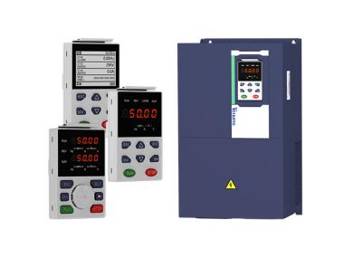
45kw 60hp ac drive inverter vfd for pump fan air compressor vfd
Item | Specifiation | |
Input | Inuput Voltage | 1phase/3phase 220V:200V~240V 3 phase 380V-480V:380V~480V |
Allowed Voltage fluctuation range | -15%~10% | |
Input frequency | 50Hz / 60Hz,fluctuation less than 5% | |
Output | Output Voltage | 3phase:0~input voltage |
Overload capacity | General purpose application:60S for 150% of the rated current Light load application:60S for 120% of the rated current | |
Control | Control mode | V/f control Sensorless flux vector control without PG card(SVC) Sensor speed flux vector control with PG card (VC) |
Operating mode | Speed control,Torque control(SVC and VC) | |
Speed range | 1:100 (V/f) 1:200( SVC) 1:1000 (VC) | |
Speed control accuracy | ±0.5% (V/f) ±0.2% (SVC) ±0.02% (VC) | |
Speed response | 5Hz(V/f) 20Hz(SVC) 50Hz(VC) | |
frequency range | 0.00~600.00Hz(V/f) 0.00~200.00Hz(SVC) 0.00~400.00Hz(VC) | |
Input frequency resolution | Digital setting: 0.01 Hz Analog setting: maximum frequency x 0.1% | |
Startup torque | 150%/0.5Hz(V/f) 180%/0.25Hz(SVC) 200%/0Hz(VC) | |
Torque control accuracy | SVC:within 5Hz10%,above 5Hz5% VC:3.0% | |
V/f curve | V / f curve type: straight line, multipoint, power function, V / f separation; Torque boost support: Automatic torque boost (factory setting), manual torque boost | |
Frequency giving ramp | Support linear and S curve acceleration and deceleration; 4 groups of acceleration and deceleration time, setting range 0.00s ~ 60000s | |
DC bus voltage control | Overvoltage stall control: limit the power generation of the motor by adjusting the output frequency to avoid skipping the voltage fault;
Undervoltage stall control: control the power consumption of the motor by adjusting the output frequency to avoid yaw failure
VdcMax Control: Limit the amount of power generated by the motor by adjusting the output frequency to avoid over-voltage trip; VdcMin control: Control the power consumption of the motor by adjusting the output frequency, to avoid jump undervoltage fault | |
Carrier frequency | 1kHz~12kHz(Varies depending on the type) | |
Startup method | Direct start (can be superimposed DC brake); speed tracking start |
VEIKONG inverter work together with famous brands
Modbus and Canopen communication parameter
30 Group Modbus communication parameter | ||||
P30.00 | Communication type | 0:Modbus; 1:Canopen | 0 | ★ |
P30.01 | Drive Address | 1~247 Different slaves on the same network should set different local addresses; 0 is the broadcast address, all slave inverters can be identified | 1 | ★ |
P30.02 | Modbus baud rate | 0:1200 bps; 1:2400 bps 2:4800 bps; 3:9600 bps 4:19200 bps; 5:38400 bps 6:57600 bps; 7:115200 bps | 3 | ★ |
P30.03 | Modbus data format | 0: 1-8-N-1 (1 start bit +8 data bits +1 stop bits ) 1: 1-8-E-1 (1start bit +8 data bits +1 even parity +1 stop bit) 2: 1-8-0-1 (1 star bit+8 data bits +1odd parity+1 stop bits) 3: 1-8-N-2 (1 star bit+8 data bits+2 stop bits) 4: 1-8-E-2 (1 star bits+8 data bit+1 even parity+2 stop bits) 5: 1-8-0-2 (1 start bit +8 data bits+1 odd parity+2 stop bits) | 0 | ★ |
P30.04 | Modbus response delay | 1~20msThe delay time of the local to answer the master | 2ms | ★ |
P30.05 | Modbus overtime | 0.0s(disabled)~60.0s(works for master-slave system) When this function code effective,if slave do not receive data from master overtime,it will trip as Er.485 | 0.0s | ★ |
r30.06 | Number of frames received by Modbus | Each time a frame is received, this value is incremented by 1,0 to 65535 cycles. | - | ● |
r30.07 | Number of frames that Modbus has sent | Each time a frame is sent, this value is incremented by 1,0 to 65,536 cycles. | - | ● |
r30.08 | Number of error frames received by Modbus | Each time an CRC error frame is received, this value is incremented by 1,0 to 65535 cycles; it can be used to judge the degree of communication interference. | - | ● |
P30.09 | Modbus master-slave option | 0: Slave 1: Master(sent by broadcast ) | 0 | ★ |
P30.10 | Slave memory when inverter as master | 1~9 corresponds to 0x7001~0x7009 | 1 | ☆ |
P30.11 | Data sent by Master | 0:output frequency 1:set frequency 2:output torque 3:set torque 4:PID setting 5:PID feedback 6:output current | 0 | ☆ |
P30.12 | Sending interval of Master | 0.010~10.000sAs a master, after sending one frame of data, the next frame of data is sent after this delay. | 0.1s | ☆ |
P30.13 | Receiving proportaionality factor of slave | -10.000~10.000The values of slave registers 0x7001 and 0x7002 take effect after passing through this scaling factor | 1.00 | ☆ |
P30.14 | Communication special register speed unit | 0: 0.01% 1: 0.01Hz 2: 1Rpm Some units of specific communication registers can be set by this parameter. See Appendix A for details. | 0 | ☆ |
P30.15 | Modbus response characteristics | When the format of the received frame is a write register, this parameter can be set to reply to the host. 0: Reply to the host (standard Modbus protocol) 1: Do not reply to the host (non-standard Modbus protocol) | 0 | ☆ |
31 Group Canopen communication parameter | ||||
P31.00 | CANopen communication address | 1 ~ 127 | 1 | ☆ |
P31.01 | CANopen Baud rate | 0:100k 1:125k 2:250k 3:500k 4:1M | 3 | ☆ |
P31.02 | CANopen overtime | 1ms ~ 20ms | 4ms | ☆ |
r31.07 | CANopen version number | Display the version number of the CANopen card | - | ● |
r31.08 | CANopen Working status | 0: Initialisation status 1: Disconnected 2: Connecting/Preparing- 3: Stopped 4: Operational status 5: Pre_operational | - | ● |
r31.10 | CANopen receive error count | The number of error frames received by CANopen is not saved after power off | - | ● |
r31.11 | CANopen send error count | The number of frames sent by CANopen is not saved after power off | - | ● |
r31.12 | CANopen receive frame number | The number of frames received by CANopen is not saved after power off | - | ● |
r31.14 | CANopen send frame number | The number of frames sent by CANopen is not saved after power off | - | ● |