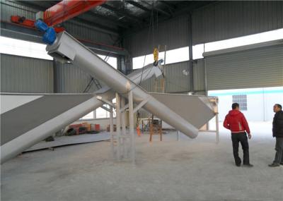
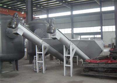
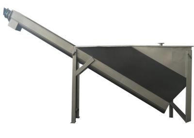
The continuous backwash sand filter is a unique system that filters liquid suspensions to the designed effluent quality, while at the same time cleaning the sand bed so the filter does not shut down during the backwash period.
Description
The continuous backwash sand filter is a unique system that filters liquid suspensions to the designed effluent quality, while at the same time cleaning the sand bed so the filter does not shut down during the backwash period. Feed water is passed upwards through the sand bed and exits the rapid sand filter as clean water. At the same time, sand can be removed from the bottom, cleaned and returned to the top. A small portion of the filtered water is used to wash the sand and leaves the filter as a reject stream.
The continuous backwash sand filter allows continuous filtration with intermittent sand washing. Operating in this mode, the system reduces the amount of reject water, increases filter performance, maximizes the airlift lifecycle, and reduces maintenance time.
Our continuous backwash sand filter is available as either a standalone package unit or a modular concrete design. The package units are constructed of either 304 SST or FRP. Internal components for both package and concrete units are built with stainless steel (SS) and/or FRP. Filters are available in 40” standard bed or 80” deep-bed design depending on the nature of the application.
A concrete, continuous backwash filter installation can be designed for any size area, allowing the technology to adapt to any size of water or wastewater treatment plant.
Concrete modules are frequently used for high-flow capacity systems, and involve placing multiple modules into a common filter cell. The modules in a filter cell share a common filter bed, where cones inside each module distribute sand to their respective airlifts and sand washers. During operation, the pressure drop remains low and even throughout all filters. Equal pressure drop ensures even distribution of feed to each filter without the need for splitter boxes or flow controls. Therefore, a typical multiple unit installation can use a common header pipe with feed connections and isolation valves for each filter.
Applications
It could be used in the treatment of industrial wastewater, surface water, reused water, drinking water plant and Municipal Wastewater Treatment Plant.
Technical parameters
Typical Data |
Influent solids |
Filtrate solids |
Tertiary Filtration |
20-50 ppm SS |
5-10 ppm SS |
Turbidity |
10-30 NTU |
0.1-0.5 NTU |
Color |
10120 ACU |
1-5 ACU |
Process Water |
10-30 NTU |
0.1-0.5 NTU |
Metal Finishing |
20-50 ppm SS |
2-5 ppm SS |
Steel Mill Scale |
50-300 ppm SS |
5-10 ppm SS |
Phosphorus Removal |
<1ppm TP |
<0.1ppm TP |
Algae Removal |
100 ppm SS |
10-20 ppm SS |
Denitrification |
10-15 ppm TN |
<3 ppm TN |
Oil Removal |
<50 ppm |