5.6. Description of operation mode
1. The default mode for powering on the regulator is "constant voltage".
2. When the "adjustment mode switch setting" parameter is set to HCOS or HCO2 (both are constant power factor mode: HCOS adjustment speed is fast, but the stability is relatively poor; HCO2 adjustment speed is relatively slow, but the stability is good. The factory default setting is HCO2, the new version of the program cancles the HCO2 mode, only retains the HCOS mode, but improves the stability), when the generator current is greater than the set value (see parameter "constant power factor switching current"), press the "Switch" key to switch to the "constant power factor" adjustment mode. The initial power factor is given as the value of the current power factor, and then the given value of the current power factor can be modified according to the "increase" or "reduce" key.
3. In the "constant power factor" adjustment mode, according to the "increase" or "reduce" key to modify the given power factor value 5 minutes later, will automatically write the "given power factor preset" parameters and save, the next grid-connected and current conditions are met will automatically switch to the "constant power factor" adjustment mode and run according to the given power factor value saved last time.
4. In the "constant power factor" adjustment mode, press the "Switch" key to switch to the "constant voltage" adjustment mode. After switching to the "constant voltage" adjustment mode for 5 minutes, the grid-connected automatic cut constant power factor operation will be turned OFF (the parameter value of "given power factor preset" will become OFF).
Note: In the "constant power factor" regulation mode operation, when the generator current is less than the set value (see the parameter "constant power factor switching current"), it will automatically return to the "constant voltage" regulation mode to ensure the good operation of the generator. If the following current value meets the conditions, it will automatically enter the "constant power factor" adjustment mode.
If the automatic switch of "constant power factor" adjustment mode has been opened after grid-connected, then the "constant voltage" lamp will blink at an interval of 0.5S before entering the "constant power factor" adjustment mode after grid-connected, and maintain the power factor at about 0.9 without manual intervention.
5. When the "Adjustment mode switch setting" parameter is set to HALF (constant control Angle), press the "Switch" key when not connected to the grid will switch between the "constant voltage"/" constant control Angle "adjustment mode. After grid-connected, it will automatically switch to the "constant control Angle" adjustment mode and lock it. Manual switching is not allowed.
This mode of operation is generally used for field debugging, field winding drying, and short circuit test of the unit.
5.7, the generator overload
When the current is greater than or equal to the overload protection setting value (see the parameter "Overload Protection Setting"), if the current is the "constant voltage" regulation mode, the regulator automatically switches to the "constant power factor" regulation mode, and the power factor is maintained at 0.99. If the current "constant power factor" regulation mode, and given less than 0.99, then will automatically increase the given power factor (excitation reduction). When exiting the overload, the original power factor setting is automatically restored (during this process, the "Constant COS" light flashes at intervals of 0.5S). This function is not valid when the "Adjust Mode Switching Settings" parameter is set to "HALF".
6. Parameter setting
Press and hold the "Display" button continuously for 3 seconds, then the digital tube flashes and enters the parameter setting interface (in general, it can meet the operation requirements without changing any parameters)
Press "Increase" or "Reduce" key to change the parameter value, press "Display" key to save the current parameter and enter the next parameter setting, when the last parameter is reached, press "Display" key to exit the parameter setting. During the parameter setting process, if no operation is performed within 8 seconds, the current parameter modification value will not be saved and the setting will be automatically exited.
1. Local address: display "AXX", can be set between 0 and 99 (XX indicates the current value, the same below).
2. Baud rate: Display "b48" or "b96", indicating that the baud rate is 4800 or 9600.
3. Adjustment factor: Displays "TXX", which can be set between 0 and 20. The default value is 20. Zero difference adjustment when set to 0. No special requirements generally do not need to adjust,
4.P parameter: Display "PXX", can be set between 1-60, factory default value 40.
5.I parameter: Display "IXX", can be set between 1-2, factory default 1.
6.D parameter: Display "DXX", can be set between 1-60, factory default 24.
Note: The adjustment coefficient and PID parameters are used to adjust the response speed and response performance of the generator in real time operation. The setting at the factory has been able to meet the needs of most unit characteristics, please do not modify at will.
7. Power grid voltage calibration: At this time, "E.XX" is displayed, indicating the current measured power grid voltage value.
8. Generator current calibration: "I.XX" is displayed at this time, indicating the current measured C-phase current value.
Calibration method: The voltage current shows the percentage value of the current measurement (i.e., the actual value/rating x 100). If the displayed percentage value is different from the actual percentage value, you can use the "Increase" or "Reduce" key to modify. For example, the current is 80A and the rated current is 200A, then the display should display I040 (algorithm: 80/200×100=40), and the grid voltage calibration is the same. If the error is not large, it does not need to be calibrated and does not affect the operation (the "current transformer ratio" parameter should be set before the generator current calibration).
9. Reserved parameter: display "L.XX", the system reserved parameter, can not be changed.
10. Adjust mode switching Settings: At this time, "HXXX" is displayed, which can be switched between HCOS, HCO2, and HALF. The factory default value is "HCO2" (the new version of the program has canceled HCO2, and the default value is HCOS).
11. Preset for the given power factor: At this time, "YXXX" is displayed, which can be set between 0.20-0.99. When the value is equal to 0.99, then press the "enhancement" key to display as "OFF" to turn off this parameter.
12. Excitation given voltage setting: at this time, "UXXX" is displayed, which can be set between 50-100, and the initial voltage value after excitation is set (the set value is less than 80, the grid voltage tracking is invalid). The factory default is 90.
13. Phase measurement compensation: "rXX" is displayed at this time, which can be set between -50 and +50 to correct the power factor measurement value (current measurement value - compensation value). The factory default value is 0.
14. Sync Angle compensation: At this time, "n0XX" is displayed, which can be set between 0 and 60 degrees to modify sync Angle lag, and the factory default is 0 (this parameter is used for manufacturer testing).
Constant power factor switching current: at this time, "OXX" is displayed, which can be set between 6-50, indicating how much current can be manually or automatically switched to the "constant power factor" adjustment mode. The factory default is 10.
16. Isolated network mode: At this time, "GXX" is displayed, and the factory default is 0, indicating that it is off. When the generator is running alone or several generators are networking alone. Select "1" when the automatic constant power factor switching function is disabled, but can be manually switched. When selecting "2", both automatic constant power factor switching and manual switching are prohibited, and underexcitation is not judged. Under normal circumstances, the lone network mode can be selected 2.
17. Current transformer ratio: At this time, "b. XX" is displayed, and the factory default is 80. Its value is (rated current of generator/rated current of primary side of current transformer) ×100. If the rated current of the generator is 400A, select a 500A/5A current transformer, and this parameter is set to 400/500 x 100=80.
18. Overload protection setting: "JXXX" is displayed at this time, and the factory default is 120. It can be set between 60 and 130 (corresponding to 60% to 130% rated current).
19. High frequency magnetic off setting: At this time, "FXXX" is displayed, which can be set between 52HZ-100HZ. When the generator frequency is greater than the set value, the magnetic is automatically off. The factory default is 100HZ(the regulator frequency measurement range is 16HZ-99HZ, set 100, actually does not work).
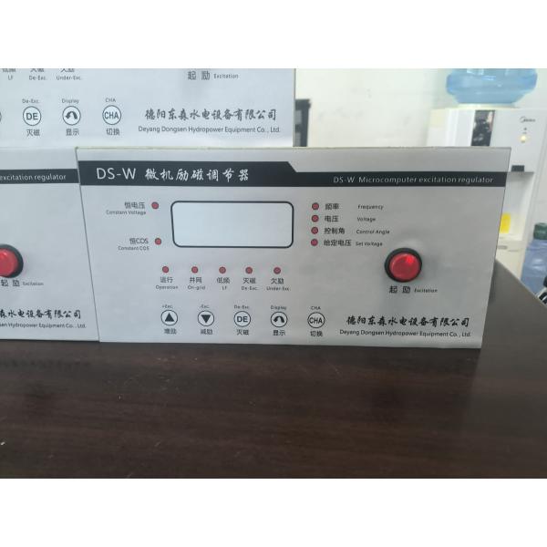
This Turbine Spare Parts product features an easy-to-install Hydrogenerator excitation regulator that is compatible with a variety of systems. With a weight of just 3kg, it can be packed and shipped in a pallet, carton, or wooden case for your convenience.
Size | Standard |
Weight | 3kg |
Frequency | 50HZ60HZ |
Compatibility | Universal |
Condition | New |
Materials | Cast Iron, Stainless Steel Or Aluminum |
Applicable Medium | Water |
Warranty | 1 Year |
Connecting Format | Flanged Ends |
Type | Hydrogenerator excitation regulator |
The Hydrogenerator excitation regulator - DS-W is designed to work with turbines that have a frequency of either 50HZ or 60HZ. This makes it versatile and suitable for use in a wide range of power generation scenarios.
One of the key applications of this product is in the maintenance and repair of hydroelectric power turbines. The Hydrogenerator excitation regulator - DS-W is a vital component of these turbines and is used to regulate the excitation of the generator. This helps to ensure that the turbine operates efficiently and effectively, maximizing power generation and minimizing downtime.
Another key application of the Hydrogenerator excitation regulator - DS-W is in the installation of new turbines. When installing a new hydroelectric power turbine, it is essential to have high-quality spare parts and components to ensure that the turbine operates correctly. The Hydrogenerator excitation regulator - DS-W is an essential component of the turbine and will help to ensure that it operates efficiently and effectively from the moment it is installed.
The Hydrogenerator excitation regulator - DS-W is suitable for use in a wide range of scenarios and applications. It is particularly useful in power generation scenarios where reliable and efficient operation is essential. This product is lightweight, weighing only 3kg, making it easy to transport and install.
The Hydrogenerator excitation regulator - DS-W is designed to work with a range of equipment and machinery. It is compatible with machining services, ensuring that it can be easily integrated into existing power generation systems.
In summary, the Hydrogenerator excitation regulator - DS-W is a high-quality, reliable, and versatile spare part designed for use in hydroelectric power turbines. Its applications include maintenance and repair of existing turbines, as well as installation of new turbines. This product is lightweight and compatible with a range of equipment and machinery, making it easy to transport and install.
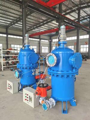
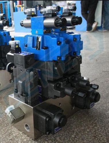
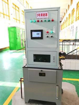
Our turbine spare parts are designed and manufactured to meet the highest industry standards and ensure optimal performance and longevity. We offer a range of technical support and services to help our customers get the most out of their turbine spare parts:
Our team of experienced technicians and engineers is dedicated to providing timely and effective solutions to any issues or concerns our customers may have. Contact us for more information on our technical support and services.