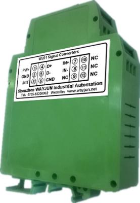
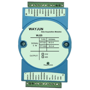
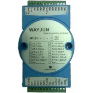
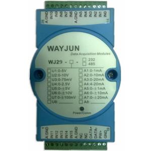
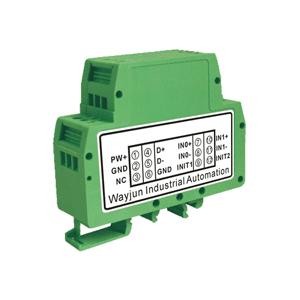
mall size,low price, WJ20 series two channels 4-20mA/0-10V/0-5V to RS485/232 Converter with MODBUS
Features:
>> Two channels analog signal acquisition,isolated RS-485/232 output
>> 16-bit AD converter,testing accuracy>0.1%
>> Can Program and calibrate modules accuracy via RS-485/232 interface
>> Signal input/output: 3000VDC Isolation
>> Wide Power supply:8~32VDC
>> High reliability,easy programming,easy installation.
>> Can program setting module address,baud rate
>> 0-5V/0-10V voltage signal or 4-20mA/0-20mA current signal input
>> Defaults MODBUS RTU communication protocol
>> DIN35 Rail-mounted
>> Dimension: 79.0x69.5x25.0 mm
Applications:
>> Signal testing/monitoring/control
>> RS-232/485 industrial automation control system
>> Industrial field signal isolation
>> Process Monitoring & Control
>> Test sensors signal
>> Laboratory Data Acquisition
>> Medical machine monitoring
>> 4-20mA/0-5V signal acquisition
MODBUS RTU communication protocol:
Module default protocol is MODBUS RTU communications protocol, the default address is 01, baud rate is 9600, data format is 10bits, 1 start bit, 8bits data bit, 1 stop bit, no check.
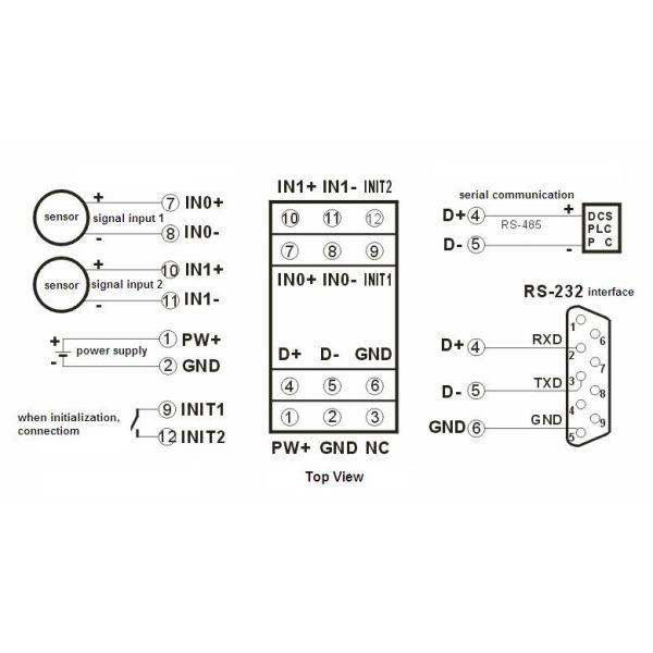
If you forget the module address and baud rate, you can shorten INIT1(PIN 9) to INIT2(PIN 12), and then restart the module power supply, the module restored to the default state temporarily: address 01, baud rate is 9600.
Users can query the address, baud rate and communication protocol register 40201-40203, get the module actual address, baud rate and communication protocol, also you can follow the need to modify the address, baud rate and communication protocol. Please note MODBUS communication please set register 40203 to 1, otherwise it can not MODBUS communication. When the INIT1(PIN 9) is turned off to INIT2(PIN 12), restart the module power supply, the module will re-set the actual address and baud rate to run.
Support MODBUS RTU communication protocol Function Code 03(Read Holding Registers) and Function Code 06(set a single Register), command format as standard MODBUS RTU protocol.
PIN | Name | Function | PIN | Name | Function |
1 | PW+ | Power+ | 7 | IN0+ | Analog signal input 0+ |
2 | GND | Power- | 8 | IN0- | Analog signal input 0- |
3 | INIT | Initialization state set | 9 | INIT1 | Initial state setting |
4 | D+ | RS-485 signal+ | 10 | IN1+ | Analog signal input 1+ |
5 | D- | RS-485 signal- | 11 | IN1- | Analog signal input 1- |
6 | GND | Power-,Output port ground | 12 | INIT2 | Initial state setting |
Example 1: If the module address is 01, hexadecimal sent: 010300000001840A, to get the register data 40001.
01 | 03 | 00 | 00 | 00 | 01 | 84 | 0A |
Module address | Read holding register | Register address High | Register address low | Register quantity high | Register quantity low | CRC check low | CRC check high |