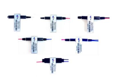
ETERN Fiber-Optical Switch Mini 1X4, 1X8-- Mini Size,Short switch time and low insertion loss
ETERN fiber-optic switches are designed based on refraction optical principle which reduces moving part position sensitivity. It featuresexcellent mechanical and optical performance and unify different switch configuration of Mini 1x4 and Mini 1x8 onto the same compact package. The products are Telcordia GR-1073-CORE qualified, and RoHS complaint.
Features | Applications |
Mini Size | Network Monitor System |
Short Switch Time | Remote Fiber Testing System |
Low Insertion Loss & Cross Talk | Module & System Integration |
Wide Operating Wavelength Range | Instrumentation |
Performance Specification
Parameter | Units | Single-Mode | |
Operating Wavelength | nm | 1290~1330 and/or 1525~1610 | |
Insertion Loss1 | 1x4 | dB | ≤ 1.0 |
1x8 | ≤ 1.2 | ||
Return Loss1 | dB | ≥ 45 | |
Polarization Dependent Loss | dB | ≤ 0.1 | |
Wavelength Dependent Loss | dB | ≤ 0.2 | |
Crosstalk | dB | ≥ 60 | |
Repeatability | dB | ≤ ±0.05 | |
Switch Time | ms | ≤ 15 | |
Durability | times | ≥ 107 | |
Switch Voltage | VDC | 2.7~3.3 or 4.5~5.5 | |
Switch Current | Latching | mA | 54~66@3V Driving or 36~44@5V Driving |
Power Handling | mW | ≤ 500 | |
Operating Temperature | °C | -5~+65 | |
Operation Humidity | %RH | 5~95 | |
Storage Temperature | °C | -40~+85 | |
Storage Humidity | %RH | 5~95 | |
Fiber Type | Corning SMF-28e fiber | ||
Pigtail Type | 900mm loose tube | ||
Package Dimension | mm | 55.0L x 44.0W x 11.9H |
Note: 1. Measured without connectors; IL will be 0.3dB worse and RL will be 5dB lower with connectors
Electrical PINs Definition
Mini 1x4 Switch | Control Input | Status Output | Common Input | ||||||||||||
1A | 1B | 2A | 2B | 3A | 3B | 4A | 4B | S1 | S2 | S3 | S4 | V+ | GND | ||
Pin1 | Pin2 | Pin3 | Pin4 | Pin5 | Pin6 | Pin7 | Pin8 | Pin9 | Pin10 | Pin11 | Pin12 | Pin13 | Pin14 | ||
Com-P1 | V+ | 0V | 0V | V+ | 0V | V+ | X | X | V+ | GND | GND | GND | V+ | GND | |
Com-P2 | 0V | V+ | V+ | 0V | 0V | V+ | X | X | GND | V+ | GND | GND | V+ | GND | |
Com-P3 | 0V | V+ | 0V | V+ | V+ | 0V | X | X | GND | GND | V+ | GND | V+ | GND | |
Com-P4 | 0V | V+ | 0V | V+ | 0V | V+ | X | X | GND | GND | GND | GND | V+ | GND |
Mini 1x8 Switch | Control Input | Status Output | Common Input | ||||||||||||
1A | 1B | 2A | 2B | 3A | 3B | 4A | 4B | S1 | S2 | S3 | S4 | V+ | GND | ||
Pin1 | Pin2 | Pin3 | Pin4 | Pin5 | Pin6 | Pin7 | Pin8 | Pin9 | Pin10 | Pin11 | Pin12 | Pin13 | Pin14 | ||
Com-P1 | V+ | 0V | 0V | V+ | 0V | V+ | 0V | V+ | V+ | GND | GND | GND | V+ | GND | |
Com-P2 | 0V | V+ | V+ | 0V | 0V | V+ | 0V | V+ | GND | V+ | GND | GND | V+ | GND | |
Com-P3 | 0V | V+ | 0V | V+ | V+ | 0V | 0V | V+ | GND | GND | V+ | GND | V+ | GND | |
Com-P4 | 0V | V+ | 0V | V+ | 0V | V+ | 0V | V+ | GND | GND | GND | GND | V+ | GND | |
Com-P5 | V+ | 0V | 0V | V+ | 0V | V+ | V+ | 0V | V+ | GND | GND | V+ | V+ | GND | |
Com-P6 | 0V | V+ | V+ | 0V | 0V | V+ | V+ | 0V | GND | V+ | GND | V+ | V+ | GND | |
Com-P7 | 0V | V+ | 0V | V+ | V+ | 0V | V+ | 0V | GND | GND | V+ | V+ | V+ | GND | |
Com-P8 | 0V | V+ | 0V | V+ | 0V | V+ | V+ | 0V | GND | GND | GND | V+ | V+ | GND |
Function Diagram