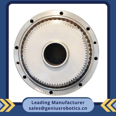
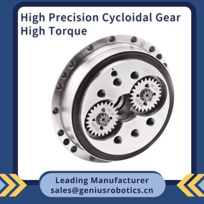
Accurate Reduction Gear Ratio And Rpm Transmission, Same Model As Nabtesco Rv-100C
The importance of RV reduction gear for industrial robots
Among all the core components of industrial robots,RV reduction gear are the most critical.
The cost structure of industrial robots is roughly as follows: 22% for the body, 25% for the servo system, 38% for the reducer, 10% for the control system, and 5%. A simple analysis of the cost of domestic 6 - axis industrial robots shows that the cost of both the reducer and the servo motor exceeds 50% of the total cost.
The first to fourth joints of industrial robots all use RV reducers, and the fifth and sixth joints of light - duty industrial robots may use harmonic reducers. RV reducers are required for all joints of heavy - duty industrial robots. On average, each industrial robot uses 4.5 RV reducers.
Features of RV reduction gear
1. Less than 1 arc - min Backlash
2. Strong impact resistance
3. Very compact with high torsional rigidity
4. Component in - line version for greater design and space saving flexibility
5. Large transmission ratio range
6. High transmission efficiency
7. Long working life, the gear unit is operated at rated conditions with a life of > 6000 hours.
It is not advisable to operate for longer than the rated speed or rated torque, otherwise the life will be reduced.
To ensure the accuracy and longevity of the gear unit, please replace the grease after every 2000 hours of operation.
8. The gear unit is operated at rated speed with a noise of < 75 dB.
The noise level is related to installation accuracy, lubrication, temperature, load and other factors.
Application of RV reduction gear
Industrial Robot , SCARA, Positioning axis , AGV, Machine tool, Medical equipment, Indexing mechanism, Rotary table, Elevator platform ,
Wind energy mechanism , Gantry , Aeronautics
RV reduction gear RV-100C -36.75 technical parameters
Model | 10C | 27C | 50C | 100C | 120C | 200C | 320C | 320CA |
Reduction ratio * | 27 | 36.57 | 32.54 | 36.75 | 36.75 | 34.86 | 35.61 | 140 210 |
Rated torque (Nm) * | 100 | 270 | 500 | 1000 | 1200 | 2000 | 3200 | 3200 |
Maximum working torque (Nm) | 250 | 675 | 1250 | 2500 | 3000 | 5000 | 8000 | 8000 |
Maximum impact torque (Nm) | 500 | 1350 | 2500 | 5000 | 6000 | 10000 | 16000 | 16000 |
Maximum output speed (r/min) | 80 | 60 | 50 | 40 | 40 | 30 | 25 | 25 |
Backlash/idle stroke (arc.min) | 1 | 1 | 0.8 | 0.8 | 0.8 | 0.6 | 0.6 | 0.6 |
Torsional rigidity (Nm/arc.min) | 46 | 145 | 255 | 510 | 600 | 976 | 1960 | 1960 |
Allowable torque (Nm) | 680 | 980 | 1760 | 2450 | 2450 | 8800 | 20550 | 20550 |
Allowable thrust force (N) | 5880 | 8800 | 11750 | 13700 | 13700 | 19600 | 29350 | 29350 |
Weight (kg) | 4.5 | 8.5 | 14.5 | 19.6 | 21 | 55.5 | 80 | 80 |
* Note: This gear reduction ratio is the unit gear reduction ratio, excluding that generated by the input gear and the two way big gear
* The output torque is the rated torque when the output speed is at 15 r/min
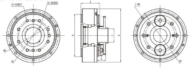
RV reduction gear RV-100C -36.75 external dimension table
Unit:mm
Model | 10C | 27C | 50C | 100C | 120C | 200C | 320C | 320CA |
A | 59 | 67.5 | 79 | 82.5 | 82.5 | 120.5 | 126 | 148.5 |
¢B | 110 h7 | 140 h7 | 176 h7 | 199 h7 | 199 h7 | 260 h7 | 340 h7 | 360 h7 |
¢C | 31 | 43 | 57 | 71 | 71 | 70 | 138 | 132 |
¢D | 146 h7 | 181 h7 | 222 h7 | 250 h7 | 250 h7 | 346 h7 | 440 h7 | 450 h7 |
E | 26.35±0.6 | 31.35±0.65 | 34.35±0.65 | 39.35±0.65 | 39.35±0.65 | 56.2±0.85 | 71.75±0.9 | - |
F1 | 6 | 8 | 9 | 9 | 6 | 9 | 9 | 12 |
F2 | M8 | M8 | M10 | M12 | ¢5 | M16 | ¢20 | M16 |
F3 | 15 | 18 | 20 | 20 | - | 25 | - | 25 |
¢G | 82 | 116 | 133 | 160 | 140 | 194 | 252 | 328 |
H1 | 4 | 4 | 4 | 6 | - | 4 | 4 | 3 |
H2 | M3 | M4 | M4 | M6 | - | M6 | M6 | M6 |
H3 | 8 | 8 | 10 | 10 | - | 13 | 10 | 12 |
¢I | 40 | 56 | 73 | 83 | - | 116 | 152 | 144 |
J | 8 | 12 | 8 | 14 | 14 | 8 | 18 | 16 |
¢K | 6.6 | 6.6 | 9 | 11 | M10 | 13 | M12 | 13 |
¢L | 134 | 169 | 208 | 233 | 233 | 324 | 415 | 425 |
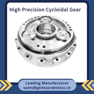
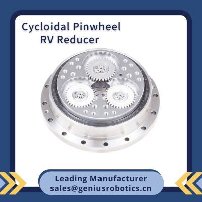
Structure principle of RV reduction gear
Input shaft / planetary gear
Form the'1st stage planetary gear reduction, realizing different gear reduction ratio through the changing of the gear.
Pin shell / pin / cycloid gear
Form the 2nd stage gear reduction, achieving high rigidity and high accuracy through the cycloid meshing rate higher than 80% and the nearly zero - backlash quality fit.
Crank shaft / output shaft
Realizing the transmmision and output of the torque by connection the 1st and 2nd stage gear reduction mechanism.
Support bearing
Provides extremely high bending moments and load bearing capacity.
Installation of RV gear reducer
Please refer to the installation drawing for the actual mounting