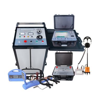
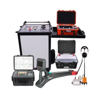
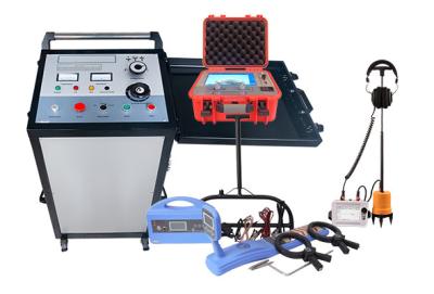
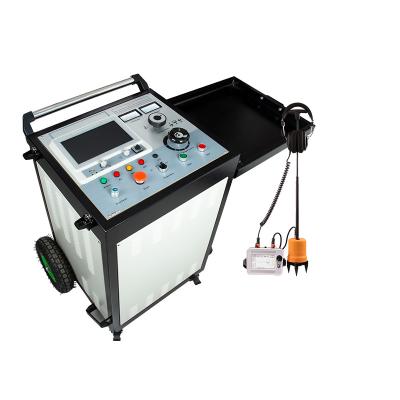
Underground cable fault locator system For 10kV 11kV and below voltage underground cable fault detection

I. System purpose:
- Accurately and quickly detect the main insulation failure of power cables; calibrate the cable length; accurately detect the direction and depth of the cable buried.
- Proof –testing of the cable with the standard D.C
- Finding the Fault –Distance on a cable.
- Pin- Pointing of cable faults on the ground.
- Tracing path-underground cables.
- Selecting a cable from a cable bundle.
II. System Configuration
| Product name | Item | Qty. | Remarks |
| Cable fault pre locator | XHGG502 | 1unit | Test method: Low voltage pulse(tdr), high voltage flashover(ICE, decay, ARC-single shot), multiple pulse ARC |
| Cable pinpoint locator | XHDD503C | 1 unit | Digital, acoustic and Magnetic Synchronization |
| Cable pipe locator | XHGX507 | 1unit | Test cable path, current , depth, identify live and uncharged cables, locate low resistance fault to ground |
| Portable High voltage pulse generator | XHHV535-4Z | 1 unit | 0-28kV, Discharge power 0-1568J |
III. Technical description of system components
Cable Fault Pre-location
Determination of the distance of the cable fault (in meters or feet) from the test end is defined as pre-location of the cable fault. This is a critical aspect, as precise pre-location of the cable fault reduces the time taken for final fault location when compared to the conventional surge generator and pinpointed method. Pre-location uses low voltage methods such as time-domain reflectometer (TDR) and high voltage methods such as SIM, ARC, MIM, ICM/ICE & voltage decay method.
1,Cable fault pre-locator XHGG502
Introduction
XHGG502 Cable Fault Pre Locator is a special instrument for measuring and analyzing power cable status and fault distance. It combines modern electronic technology and computer technology to realize signal filtering, acquisition, data processing, graphic display and graphic analysis to complete cable speed measurement, cable Length test, cable fault distance test.
Main unit Pulse Coupler (multiple pulse sampler)
Main features
• The reflected signal sent by the pulse coupler is automatically displayed, and the full-length waveform of the cable open circuit is displayed at the same time.
• Automatic calculation and display of fault distance;
• It has the function of storing massive test waveforms: the waveforms obtained from the field test can be conveniently stored in the instrument according to the specified order, and can be recalled and observed at any time;
• With standard printer USB interface;
• Simple operation and high reliability. Has a very high cost performance;
• Built-in polymer lithium battery power supply, which can test cable open circuit and low resistance short circuit fault in no power supply environment.
The test working modes of XHGG502 ARC cable fault pre locator include low voltage pulse method, high voltage flashover method, and multiple pulse method. Here focus on the multiple pulse method that is different from other devices.
The purpose of using the multiple pulse method to test the cable fault is to make the sent low-voltage test pulse effectively avoid the cosine large oscillation interference that occurs at the moment of the high-voltage impact of the faulty cable, and obtain a standard and clear similar short-circuit during the relatively stable short-circuit arc at the fault point. The echo of the fault, and there is a large choice of ideal test waveforms.
Different impulse high voltages, different cable lengths, different cable fault distances, and the period and duration of large cosine oscillations are very different. The waveform collected by the simple secondary pulse method is often disturbed by the large cosine oscillation due to insufficient transmission delay time, and the waveform is chaotic and difficult to analyze. It can only be ensured by adjusting the delayed launch time of the test pulse or using a medium-voltage arc-extending device, which increases the difficulty of operation and the weight and cost of the equipment. The multiple pulse method just overcomes these difficulties and greatly simplifies the testing procedures. Eight sets of test waveforms are obtained from the high-voltage flashover process of one impact, and there are always several sets of waveforms that are convenient for fault distance interpretation. This is also the advantage of the multiple pulse method compared with the second pulse method.
Operation system show
Testing cable fault distance under high voltage flashover test mode, this test method is suitable for detecting various of high resistance fault. There is one waveform on the screen. By adjusting the position of the two cursor lines, the fault distance can be determined.
Testing cable fault distance under ARC(multi-shot) test mode, this test method is suitable for detecting various of high resistance fault. Especially for waveforms that are difficult to analyze, such as low-resistance and submerged cable faults, the multiple pulse method is easier to analyze and can help users quickly determine the fault distance.
Testing cable fault distance under low voltage pulse test mode. For low resistance open circuit (break) and short circuit faults, the fault distance can be easily measured.
Technical parameters
| Sampling frequency | 400MHz |
| Minimum resolution | 0.5m (100m/us) |
| Low voltage pulse width | 0.2uS/2uS/4uS |
| Test blind zone | ≤20m |
| Ranging range | ≥68km |
| Measurement error | ≤±(0.5%×L+1m), L is the cable length |
| There are three test cable lengths | <1km (short distance); <3km (medium distance); >3km (long distance), (low-voltage pulse test amplitude: 400Vpp) |
| Pulse coupler withstand voltage | DC 35kV |
| Working conditions | temperature -25℃~+65℃, relative humidity 85%, atmospheric pressure 750±30mmHg |
| Volume and weight | Cable fault tester 430×380×220mm-10kg; Pulse coupler 430×380×220mm-10kg |
Panel introduction
1 Display: 12.1-inch industrial-grade touch screen;
2 Communication: low-voltage pulse method pulse signal output interface, high-voltage flashover method sampler receiving signal input interface;
3 Grounding: safety grounding terminal;
4 Power indicator: Indicates the internal battery power, displayed in 4 grids;
5 USB-1: External wireless network card and USB communication device;
6 USB-2: External wireless network card and USB communication device;
7 Power switch: "I" position, use AC 220V power supply to supply power to the system;
The “II” gear uses the internal battery to power the system; when the “power socket” is connected to the AC 220V power supply, it also charges the battery at the same time;
"O" gear, turn off the system power;
8 Power socket: working power supply of the instrument, AC 220V connection port;
9 Fuse: the place where the fuse of the AC 220V power supply system is installed;
10 Self-check: transmit signals under multiple pulses;
11 On/Off: Turn on and off the working power of the industrial computer;
12 Amplitude: Adjust the amplitude knob when collecting waveforms to change the amplitude of the collected waveforms;
13 Indicator light: the indicator light reflecting the inspection method;
14 Displacement: Adjust the displacement knob when acquiring waveforms to change the baseline height of the acquired waveforms;
Packing list
Cable Route Tracing, Pinpointing, Cable Identification, Repair & Re-test
2,Cable route tracer(Cable path comprehensive tester) (XHGX507)
Cable Route Tracing
Often, pinpointing the cable fault takes larger time as the route tracing of the cable under test (CUT) has not been carried out or cable route is unknown. The exact route of the cable is determined by using audio induction method.
In the audio induction method, a stable, high frequency AC sinusoidal signal from an audio frequency generator is injected into the CUT at test end, which completes its path through earth and available on the entire cable lay. A route tracer sensor coil parallel to ground connected to an audio receiver picks up the signals, which is displayed on receiver visually in the form of graphs and in the form of sound captured through headphones.Strongest signal is received exactly above the cable and signal strength reduces if the search coil is either side of the cable or away from it. The cable route is determined by finding maximum audio signals on audio receiver and headphones.
Description
XHGX507 underground cable pipe locator is mainly used for cable fault location, cable identification, cable path and depth measurement. It can complete tasks that could only be accomplished by a few sets of instruments in the past.
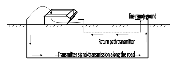
Working principle
The underground cable pipe locator is designed based on the electromagnetic induction method and the application of the communication principle.
1.The electromagnetic signal is generated by the transmitter, and the signal is transmitted to the underground cable under test through different transmission connection methods.
2.After the underground cable induces the electromagnetic signal, an induced current is generated on the cable, and the induced current propagates along the cable to the distance.
3.In the process of current propagation, electromagnetic waves are radiated to the ground through the underground cable. When the receiver detects on the ground, the electromagnetic wave signal will be received on the ground above the cable.
4. The position, direction and fault of the underground cable can be judged by the change of the received signal strength.
Features
●The large-screen LCD displays the signal strength, and the bar, arrows and voice prompts make it easy for the operator to judge the underground position of the cable and the fault point. One person can do it all.
●All-digital design, clear large-screen LCD graphic display and reliable positioning
●Portable and lightweight, easy to carry
●Built-in rechargeable battery
●Built-in ohmmeter to measure cable loop resistance
●Can be used to detect insulation faults up to 2MΩ to ground
●With backlight function to adapt to night operation
●Built-in ohmmeter to measure cable loop resistance
●Display cable depth and current
Main components
This cable pipe locator is mainly composed of transmitter and receiver, with accessories of two clamps, one A-frame and necessary connection wires.
Technical Parameters
Transmitter
| Working frequency | low frequency (815Hz), intermediate frequency (8kHz), high frequency (33 kHz), radio frequency (83 kHz) |
| Working mode | direct connection method, coupling method (caliper method), induction method |
| Matching load | 5 ohms—3000 ohms |
| Impedance display | 5 digits |
| Overheating and over current | automatic protection |
| Power output | low gear, middle gear, high gear |
Receiver
| Working frequency | low frequency (815Hz), intermediate frequency (8kHz), high frequency (33 kHz), radio frequency (83 kHz), Passive frequency 50Hz |
| Antenna mode | valley method (zero value mode), crest method (peak mode), step voltage method and clamp current method (A-frame) |
| Current indication | display the effective current value of the cable under test (unit: mA) |
| Working temperature | -10℃+55℃ |
| Power indicator | graphic display |
| Battery life | continuous work> 8 hours: intermittent work> 16 hours |
| Signal strength indication | ladder diagram, digital range 0-999 |
| Gain control | manual adjustment, dynamic range of 100dB |
| Detection depth | the maximum detection depth is around 10 meters |
| Maximum detection distance | The cable with good insulation can be up to 15km in the direct connection method |
| Depth measurement | press the depth key to display three digits, the maximum depth can be measured up to 10 meters |
| Accuracy | Low frequency: ±(1-5)%≤2.5m Radio frequency: ±(5-12)%≤2.5m |
Packing list
Application case
3.Cable fault pinpoint locator (XHDD503C)
Cable Fault Pinpointing
Based on the approximate fault distance calculated by Pre-locator and suspected faulty area marked by using route tracing procedure, the exact cable fault location or pinpointing of fault is carried out.
Pinpointing of High Resistance and Flashing Faults
For pinpointing high resistance and flashing faults, a HV surge is applied into the faulty cable periodically using surge generator, generating a thumping sound at the fault point and producing strong magnetic field around the cable. These acoustic and magnetic signals are picked with the help of sensor (sensitive ground microphones) and displayed simultaneously on pinpointer receiver in the form of graphs and acoustic signals are heard on the headphones. Since both the signals, acoustic and magnetic are produced at the fault point simultaneously, the exact fault point is precisely located; where the time delay between them is near to zero. The magnetic field also helps user to determine the position of sensor and resulting easy pinpointing.
Introduction
The cable fault location instrument uses the acoustic and magnetic synchronization method to determine the power cable fault point. The electronic flashover is generated by the impact discharge generator, picked up and amplified by the corresponding probe, and the precise location of the fault point is determined by auditory and visual judgment. It is a device that completes the precise positioning of the cable fault point within the rough measurement range and collects the acoustic and magnetic time difference. It integrates positioning technology, path-assisted testing and other technologies, providing multiple test modes and rich and diverse prompt information to efficiently and accurately complete cable fault location.
This fixed-point instrument is suitable for low-resistance, short-circuit, open-circuit and disconnection faults of power cables, high-frequency coaxial cables, street light cables, and buried wires made of various materials with different cross-sections and media, as well as high-resistance leakage and high-resistance flashover. Fault. The technical parameters comply with "GB/T 18268.1 Anti-interference requirements for test equipment used in industrial sites".
It complies with the standard requirements for acoustic and magnetic fixing in the standard "DL∕T 849.2-2019 General technical conditions for special testers for power equipment Part 2: Cable fault locating instrument".
Features
1. 5-inch touch-high brightness LCD ensures visibility under sunlight.
2. Adopt acoustic and magnetic synchronous positioning technology to automatically calculate the acoustic and magnetic time difference.
3. The gain value and trigger value of the acoustic signal and magnetic signal can be manually adjusted to adapt to various environments.
4. It has background noise reduction technology and can choose from a variety of filtering methods.
5. It has BNR background noise reduction and mute noise reduction functions.
6. It has path deviation indication.
7. Equipped with multi-layer physical isolation signal sensors, waterproof grade IP65.
8. Built-in large-capacity lithium battery, long standby time, equipped with fast charger.
9. Small and lightweight, easy to operate, and simple human-machine interface.
Technical indicators
| 1 | Filter parameters | All-pass: 100Hz~1600Hz. Low pass: 100Hz~300Hz. Qualcomm: 160Hz~1600Hz. Bandpass: 200Hz~600Hz. |
| 2 | Channel gain | 8 levels adjustable. |
| 3 | Magnetic channel gain | 8 levels adjustable. |
| 4 | Output gain | 16 levels (0~112db) |
| 5 | Output impedance | 350Ω |
| 6 | Acoustomagnetic positioning accuracy | less than 0.2m. |
| 7 | Path identification accuracy | less than 0.5m. |
| 8 | Power supply | 4*18650 standard lithium batteries. |
| 9 | Standby time | more than 8 hours. |
| 10 | Volume | 428L×350W×230H |
| 11 | Weight | 6.5kg. |
| 12 | Ambient temperature | -25~65℃; Relative humidity: ≤90%. |
Working principle
This device uses the acoustic and magnetic synchronization method to accurately locate faults. It is a very accurate and unique positioning method. Its principle is based on the traditional acoustic point determination method and adds the detection and application of electromagnetic signals.
When the high-voltage generator performs impact discharge on the faulty cable, the sound generated by the discharge at the fault point is transmitted to the ground. The sound signal is picked up by a high-sensitivity probe. After amplification, a "pop" sound can be heard by listening with headphones.
The built-in probe of the probe receives the magnetic field signal in real time, and uses the principle that the propagation speed of the magnetic field is much higher than the propagation speed of sound to determine the distance of the fault point by detecting the time difference between the electromagnetic signal and the sound signal. Keep moving the sensor position to find the point with the smallest acoustic-magnetic time difference, then the exact location of the fault point will be below it.
Traditional acoustic measurement legal point instruments generally only use earphones to monitor, or are supplemented by the swing of the meter pointer to identify the discharge sound at the fault point. Since the discharge sound disappears in an instant and is not much different from the ambient noise, it often brings great difficulties to operators who are not very experienced. The acoustic-magnetic synchronization method effectively avoids the above problems of the traditional acoustic measurement method.
Packing list
Operation panel introduction
1. Adjustment: Press the adjustment button to enter the adjustment interface, and rotate the adjustment button to set the adjustment parameters;
2. Power supply: Turn on and off the power supply of the system. When turning on the system, you need to press and hold the power button for 3 to 4 seconds until you hear a long "beep" sound, then you can lift the button; when turning off, you need to press and hold the power button for 3 to 4 seconds;
3. Display: 5-inch touch display.
1 Sensor: Probe sensor connection port;
2 Charging: charger connection port;
3 Dedicated headphone jack.
Interface and function introduction
The operation interface includes a waveform display area and a parameter adjustment area. The functions of each part are introduced one by one according to the logo in the above figure.
1/2: Sound gain setting/sound trigger setting
3/4: Magnetic field gain setting/magnetic field trigger setting
5: Probe indication
6: All-pass filtering
Low-pass filtering
High-pass filtering
Band-pass filtering
7.Mute setting
8.BNR settings
9.Volume setting
10.Power display
11.Sound intensity: sound intensity indication and corresponding numerical display.
12.Electromagnetic signal: Initialization completed, you can sample the logo (lightning is yellow); mute or touch sensor logo (lightning is white).
13.Magnetic field strength: magnetic field strength indication and corresponding numerical display.
14.Four sets of acoustic and magnetic time difference data display, showing the acoustic and magnetic time difference for user reference to improve the accuracy of fixed point.
4.XHHV535-4Z Portable High Voltage Surge Generator
To pinpoint high resistance and flicker faults, a surge generator is used to periodically apply high voltage surges into the faulty cable, producing a banging sound at the fault point and a strong magnetic field around the cable. These acoustic and magnetic signals are picked up with the help of sensors (sensitive ground microphones) and displayed simultaneously on the positioning receiver in the form of a graphic, and the acoustic signal can be heard through headphones. Since the acoustic and magnetic signals are generated at the fault point at the same time, the exact fault point can be pinpointed; the time delay between them is close to zero. The magnetic field can also help users determine the location of the sensor, making it easy to pinpoint the fault point.
Description
The high-voltage pulse generator fully complies with DL/T846-2016 "General Technical Conditions for High Voltage Test Equipment" and DL/T474-2017 "Guidelines for the Implementation of Field Insulation Tests". It is mainly used for impact discharge during fault testing of cables with voltage levels of 35kV and below; it can also be used for DC withstand voltage tests of other electrical equipment.
This device integrates DC high-voltage source, energy storage capacitor, and discharge ball gap into one. This equipment completely replaces the traditional test transformer weighing hundreds of kilograms, operation box and pulse energy storage capacitor (generally a set of 5kVA transformer weighs more than 60 kg, and the control box more than 30 kilograms, and more than 20 kilograms of pulse energy storage capacitors).
The power supply adopts high-precision, high-stability special high-voltage electronic components and high-frequency high-voltage technology, which makes the whole machine simple in structure and ultra-light in weight. The pulse generator adopts humanized design and operation mode, which is safe and reliable. It really achieves the effect of not being damaged by impact, and it can also work normally when the high voltage is short-circuited to the ground. It is currently the lightest and most user-friendly portable DC impact high-voltage equipment. It is an ideal product for power cable fault detection.
Technical parameters
| Impact high voltage | 0~28KV |
| High voltage partial pressure | 2.5 level |
| Built-in capacitor | 4μF |
| Discharge power | 1568J |
| Impact power | 400W |
| Over temperature protection | 85℃ |
| Volume(mm) | 420L×325W×480H |
| Weight | not more than 40kg |
| Power supply | AC220V±10%, 50Hz±1Hz(60Hz can be customized) |
| Ambient temperature | -20~+65℃ |
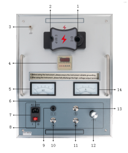
Panel introduction
1. High voltage output (DC): When DC withstand voltage, connect the high-voltage output line.
2. High voltage output (EMP): During impulse discharge, connect the high-voltage output line.
3. Safety ground: The instrument casing is grounded to prevent electrification of the instrument casing or to personnel.
4. Time setting: Set the discharge time interval.
5. Voltmeter: High voltage output voltage indication, used to display the voltage value in real time.
6. Power socket: Instrument working power supply, AC 220V ± 10%/50Hz ± 1Hz.
7. Safety tube holder: The installation location of the safety tube in the AC 220V power supply system.
8. Power switch: "I position" indicates turning on AC 220V power to supply power to the system;
'0 gear' means turning off the AC 220V power supply to supply power to the system.
9. Overcurrent protection switch: Pressing the status indicates that the overcurrent protection function has started; When it bounces, it indicates that the instrument has triggered overcurrent protection.
10. Start button/zero position indicator light:
①When the zero position indicator light is on (yellow), it indicates that it is in the zero position state. Pressing the start button can start the high-voltage output;
②When the zero position indicator light is not on, it indicates that it is not in the zero position state. After turning the voltage adjustment knob counterclockwise to the zero position, the zero position indicator light is on, and then pressing the start button can start the high-voltage output.
11. Stop button/high voltage indicator light: When the test is completed or an abnormality occurs, press this button to cut off the high voltage output. The high voltage indicator light on indicates that the high voltage output has been activated; The high voltage indicator light is off, indicating that the high voltage output has stopped.
12. Voltage adjustment knob: used to adjust the size of the voltage; Adjust the output high pressure clockwise to increase from small to large, and counterclockwise to decrease from large to small.
13. Discharge button: In the high-voltage stop state, pressing this button can manually discharge the internal stored electricity.
14. Ammeter: indication of low voltage measuring current.
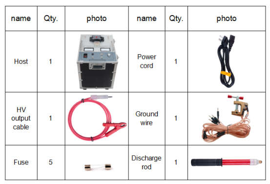
Packing list
Contact us freely if there are further questions and requirements~! Thank you!