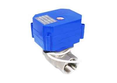
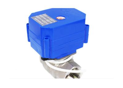
Intelligent zone heating valves, 3 way heating valves for underfloor heating systems
Product Description
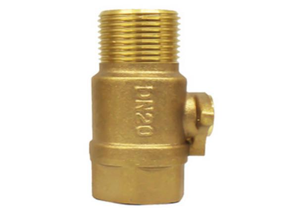
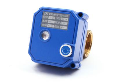
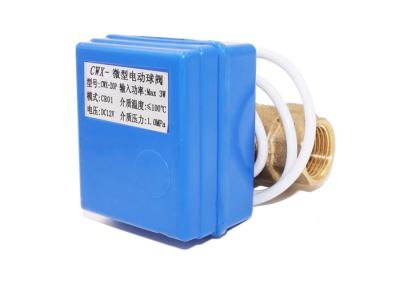
The heating control zone valves, are consisted of: mini motorized ball valve and electric actuator motor. It includes auxiliary limit switches to determine if the valve is completely open or closed. These systems use these signals to control a pump (circulator) and boiler to start pumping the hot water. The water then flows through the system, heating the zone, until the respective thermostat’s temperature setting is reached.
Features
1. Extreme long service life span ;
2. Manual Override, the valve can be operated when power failure;
3. Mini dimension and position indicator
4. Good sealing performance, IP65 enclosure
Application
Advantages
No. | Ours | Normal products |
Valve shaft seal | Quadruple seals | Dual seals |
Nut seal | Auto super anaerobic glue coating, Consistent torque tightening | Manual anaerobic glue, unevenly, non consistent torque tightening |
Seal between valve body and housing | Seal groove | none |
Torque | Smoothly and light | Heavy, non consistently |
Drainage | Yes | none |
Technical data
Model | 20P-1.0D |
Work Amp (mA) | Max 80 |
Protection | IP65 |
Power (W) | <2 |
Operate Pressure (Mpa) | PN10 |
Torque (NM) | 2 |
Dia range | DN8-32 (Straight); DN15-20 (Tee, three way) |
Open/close (S) | Straight: < 7s; Three way: <13s |
Work volt. (V) | DC3-6V, DC12V |
Media temp (℃) | 0-90 |
Control | CR01, CR02, CR05 |
Valve body material | Connection port | Diameter | D | L | H | W |
(mm) | (Kg) | |||||
Brass | Both female thread full diameter | DN8 | 8 | 46 | 31 | 0.232 |
DN10 | 8 | 46 | 31 | 0.231 | ||
DN15 | 15 | 57 | 38 | 0.308 | ||
DN20 | 15 | 66 | 38 | 0.389 | ||
DN25 | 20 | 72 | 47 | 0.478 | ||
3-way vertical | DN15 | 12 | 63 | 49 | 0.31 | |
DN20 | 15 | 66 | 53 | 0.367 | ||
Female-male thread | DN15 | 15 | 63 | 38 | 0.307 | |
DN20 | 15 | 66 | 38 | 0.337 | ||
DN32 | 20 | 76 | 50 | 0.569 | ||
Both male thread | DN15 | 15 | 68 | 38 | 0.299 |
Wiring options
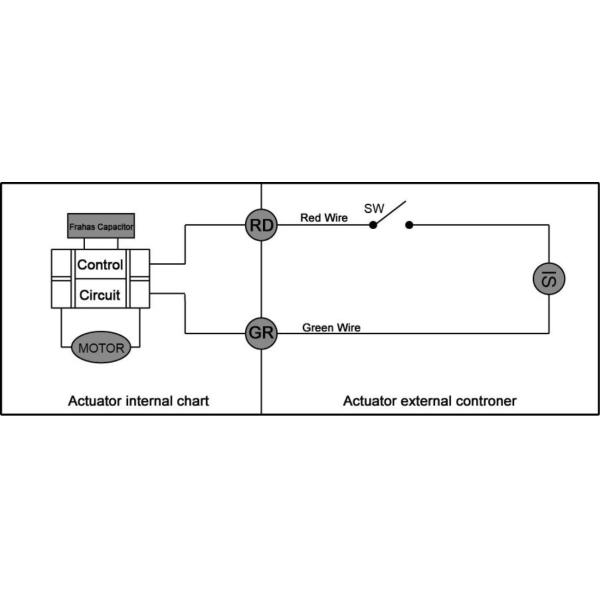
1. Connecting SW to OPEN , the valve opens , getting the position ,automatically power off, the valve remain fully open position
2. Connection SW to CLOSE , the valve close , getting the position ,automatically power off, the valve remains side passes position(fully closed)
1. Connecting SW to OPEN, the valve opens , getting the position ,automatically power off, the valve remain fully open position
2. Connection SW to CLOSED, the valve close , getting the position ,automatically power off, the valve remains side passes position (fully closed)
Note: AC24V/AC220V can only be used for 50K series electric valves
1. Connecting SW, the valve opens , getting the position ,automatically power off, thevalve remain fully open position
2. Disconnecting SW, the valve close , getting the position ,automatically power off, the valve remains side passes position (fully closed)
Note: When power is DC voltage and Red Wires is “+”,Blue wire is “—”
1. SW connecting, the valve open, getting the position and the power off automatically, the valve remains fully open/close position
2. SW disconnecting, the valve close, getting the position and power off automatically, the valve remains fully open/close position
1. Connecting SW and OPEN, the valve opens, getting the position green wire output the OLS signal, the controller tests the signal OLS, connect SW to STOP, the valve stops and remains fully open position.
2. Connecting SW and CLOSE, the valve close, getting the position red wire output the CLS signal, the controller tests the signal CLS, connect SW to STOP, the valve stops and remains fully close position.
Note: Please make sure the signal wires "red", "black" and "green" be connected at first, then connect the power wires " yellow" and "blue".
Factory show